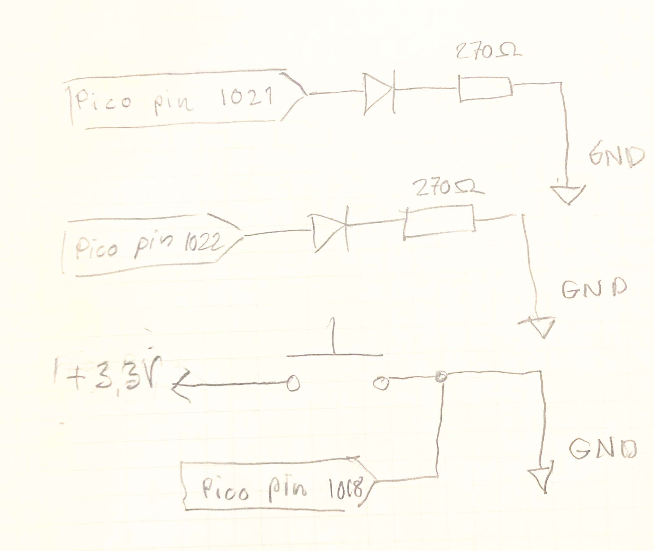
First I draw a picture as shown below. The drawing does not include the 10kohm resistor used with the switch.
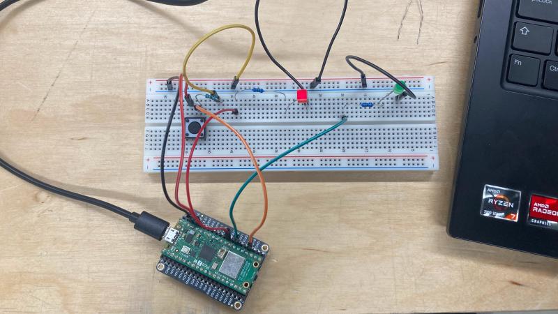
Then I connected the circuits. Looking pretty neat, am I right?
Then I wrote the program. For more details read the comments.
// Current button press
int button;
// Previous button press
int oldButton;
// Number of presses
int i = 0;

void setup() {
  //Button circut input
  pinMode(18, INPUT);
  //LED 1 circut output
  pinMode(22, OUTPUT);
  // LED 2 circut output
  pinMode(21, OUTPUT);

  Serial.begin(9600);
}

void loop() {
  oldButton = button;
// Read button press HIGH or LOW indicating whether button has been pressed
  button = digitalRead(18);
// Just printing the output
  Serial.println(button);

// If button has been pressed and previous button press was not active increase index
  if(button == HIGH && oldButton != HIGH) {
    i++;
  }
// If index out of bounds make it zero
  if (i > 2) {
    i = 0;
  }
  if (i == 1) {
// If button pressed once light first LED
    digitalWrite(22, HIGH);
    digitalWrite(21, LOW);
  } else if (i == 2) {
// If button pressed twice light second LED
    digitalWrite(22, LOW);
    digitalWrite(21, HIGH);
  } else {
// If button pressed zero or three times turn off lights
    digitalWrite(22, LOW);
    digitalWrite(21, LOW);
  }
// Little delay
  delay(10);
}